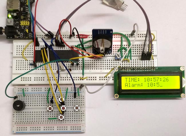
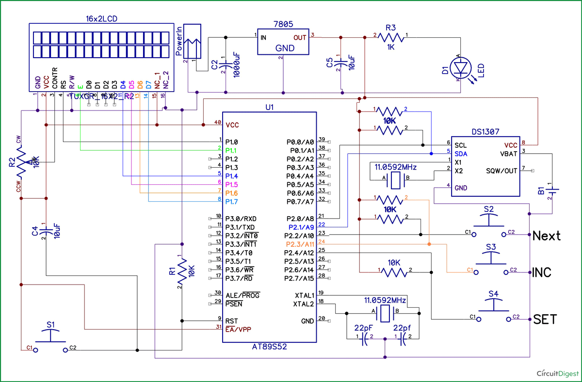
Digital Clock using 8051 Microcontroller. Codes are not working properly. After reset It shows Default time 5:5:5 and Date. With the help of 3 Switches I can Changes only Year but no other field. Also no time increments from RTC appears. I have changed the RTC Chip also but no improvement! RTC I am using DS1307. Program for timer interrupt using 8051; reception program for Serial communication using 8051; program for Serial communication using 8051; program for Serial communication using 8051; counter program using 8051; #include void main TMOD=0x50; // Timer1 is act. Timer 0 program in 8051; CAN protocol; C program to transmit a sing le. Digital Clock Circuit using 8051 and DS12C887: In this work, a real-time clock is implemented to display the time in 24 hours mode using 8051 microcontroller and RTC chip. This type of circuit is useful for displaying time and date in homes, railways, bus stands, cars, etc.
- 8051 Programming Board
- Program For Digital Clock Using 8051 Instruction
- 8051 Instruction Set Pdf
- Program For Digital Clock Using 8051 Microcontroller
You might be seeing a wall clock running with a 1.5V battery or a digital watch running with lithium or silver oxide. But, an interesting thing is, if you want to tick a clock in real time applications, the only solution is to use RTC (Real Time Clock) to get Date and Time.
In the previous tutorial, I have explained how to use RTC DS3231 with microcontroller and display date and time on LCD.
In this article, I will show how to display date and time on PC using 8051 serial communication.
RTC Schematic of DS3231


RTC code for DS3231

8051 Programming Board
This embedded C program evaluates the working of DS3231 RTC with 8051 Microcontroller and displays time and date on PC.
The below code snippet shows the macros used for RTC registers. The addresses correspond to the slave address of DS3231, second, minute, hour, second, date, month, and year, hour format.
The below code shows the macros used for i2c communication with 8051.
The below code explains the serial communication with 8051 and RTC.
The header file has been created for accessing the global variables.

Program For Digital Clock Using 8051 Instruction
The delay function has been used to set some lag for sending byte by byte to PC.
Proteus Simulation
Conclusion
I hope you understand how to use Real Time Clock (RTC) to display the date and time on the serial terminal.
8051 Instruction Set Pdf
There are multiple ways to monitor the data. It might be an LCD, PC or a serial debugger.
This DS3231 RTC code is tested on 8051 microcontroller. The date and time will be shown on the serial terminal at 9600 baud rate. The software can be putty, real term, dock light, and hyper terminal, etc.
The digital clocks are generally used to keep track of the time. It definitely displays the time, which can be easily read by anyone compared to conventional clocks. The device uses SST89E54RDA-40-C-PIE Microcontroller (MCU), a member of the FlashFlex family of 8-bit MCU that comes with 24/40 KByte of on-chip flash EEPROM program memory partitioned into two independent program memory blocks. It is 8051 compatible MCU with embedded SuperFlash memory. In addition, the device uses a seven-segment display to make the time visible for everyone.
As soon as the VCC supply is provided to the circuit, the clock starts from 00:00. The time is displayed on four seven segments (in common anode configuration) by using the concept of multiplexing. This is achieved by using timer interrupt, which is configured to refresh seven segments. The segments are refreshed a couple of times in a second for simultaneous display. The clock runs with a delay of exactly one second. The data pins (a–h) of all the segments are interconnected and receive signal from port P2 of the microcontroller. The control or enable pins (common anode) are connected to pins 1-4 of port P1 (P1.0 – P1.3). The number on 4th segment (displaying the unit digit of second) is incremented once in a second as it goes from 0 to 9. The number on 3rd segment is incremented after every 10 seconds from 0 to 5. Thus, seconds are displayed varying from 00 to 59. The digit on the 2nd segment is changed after every 60 seconds from 0 to 9 and so on.

Program For Digital Clock Using 8051 Microcontroller
The device can be seen anywhere in the world that may be noticed in the office or at home. This can be integrated to appliances for auxiliary feature and such applications may be observed in FM radios, televisions, ovens that has built in digital clocks.